All published articles of this journal are available on ScienceDirect.

Bending Performance and Evaluation of Tensile Properties of Polyester Fiber Reinforced Ductile Fiber Reinforced Cementitious Composite (PES-DFRCC)
 iD
Shoya Furukawa2
Helen Negash Shiferaw2
iD
K Hamsavathi1
iD
Toshiyuki Kanakubo3
iD
Shamsher Bahadur Singh4
iD
Authors Info & Affiliations
Abstract
Introduction/Objective
This study investigates the flexural and equivalent tensile behaviour of polyester fiber-reinforced ductile fiber-reinforced cementitious composite (PES-DFRCC) incorporating commercially available Indian-manufactured polyester fibers. The influence of fiber volume fraction on the flexural response and equivalent tensile properties was evaluated through four-point bending tests and inverse section analysis. This study presents the first experimental investigation of PES-DFRCC using this methodology and establishes its equivalent tensile stress–strain behaviour.
Methods
Beam specimens containing different polyester fiber volume fractions were tested under four-point bending in accordance with ISO 21914:2019. Load, axial deformation, and deflection measurements were recorded, and tensile properties were determined through inverse section analysis based on the observed flexural response.
Results
The PES-DFRCC specimens exhibited multiple microcracking and pronounced deflection-hardening behavior under bending. The evaluated average tensile strength ranged from 0.34 to 2.41 MPa, while the corresponding average ultimate tensile strain varied from 0.276% to 0.450%, depending on the fiber content.
Discussion
The formation of multiple microcracks contributed to enhanced ductility and energy absorption capacity, indicating the effectiveness of polyester fibers in improving the post-cracking performance of cementitious composites.
Conclusion
The newly developed PES-DFRCC demonstrated significant ductile behavior, characterized by multiple cracking, deflection hardening, and improved tensile performance. These findings highlight the potential of polyester fiber reinforcement for developing durable and ductile cementitious materials for structural applications.
1. INTRODUCTION
A fiber-reinforced cementitious composite (FRCC) is a cement-based composite material reinforced with short, randomly oriented metallic or polymeric fibers. Naaman [1] can provide insights into the historical evolution of various FRCCs. Fibers are introduced to cementitious mortar mainly to reduce crack development and propagation and also to improve tensile strength and strain capacity. The major role played by fibers in this regard is to span across developed cracks in order to improve the performance of the composite beyond cracks. By virtue of the bridging action, fiber reinforced cementitious composites have shown improvements in their ductility and toughness characteristics. In the past few decades, significant progress has been made in terms of development in matrix [2-4]. Ductile fiber-reinforced cementitious composite (DFRCC) is a cement composite material known for exhibiting multiple cracking and deflection hardening under bending loads [5]. The capacity of DFRCC to crack multiple times during bending improves key material properties, including fracture energy, toughness, deformation capacity, ultimate strain, and ductility. It may be noted that DFRCC includes cement composites such as engineered cementitious composite (ECC), high-performance fiber-reinforced composite (HPFRCC), and strain hardening cementitious composite (SHCC), which generally show strain hardening under tension loads. Among the various types of FRCC materials, DFRCC has garnered significant attention from the research community. Deflection hardening refers to the ability of the material to withstand increasing flexural loads with continued rotation, even after the formation of the first crack. This is achieved by generating multiple micro-cracks in the pure bending zone [5]. Kawamata et al. [6] studied the fracture toughness of the cement matrix in deflection-hardening DFRCC that used high-strength polyethylene (PE) fibers. Their findings indicated that the optimal fracture toughness value for the specific fiber used in their research ranges from 7.5 to 8 N/m. Matsumoto et al. [7] conducted bending tests on DFRCCs made with polyvinyl alcohol (PVA) and PE fibers. They studied the fatigue flexural response and concluded that the deformation capacity is influenced by both the number of cracks and their width, particularly concerning fiber pull-out or fiber rupture. Kanakubo [8] examined the tensile properties of four DFRCCs by performing four different types of tensile tests in a round-robin approach, concluding that the results varied based on the testing method and compaction direction. Ahmed et al. [9] developed a hybrid FRCC using steel, PE, and PVA fibers. They tested prismatic plate specimens that exhibited multiple cracking and deflection-hardening behaviour.
Lin et al. [10] investigated three-point bending tests. They found that FRCCs with straight steel and PVA fibers exhibit deflection hardening, characterised by multiple cracks. They concluded that high aspect ratio and tensile strength fibers are crucial for achieving this property. Feng et al. [11] created DFRCC plates using PVA fibers and magnesium phosphate cement (MPC) to reduce MPC's brittleness. The plates demonstrated deflection-hardening behaviour and formed multiple fine cracks under bending. Zhang et al. [12] assessed the fly-ash content on the flexural performance of deflection-hardening cementitious composites and prescribed the critical fly-ash content as 25-37.5% for 1.2% fiber volume fraction in the case of PVA fibers. The study by Bheel et al. [13] focused on the effects of varying percentages of PVA fiber on the properties of ECC. It was found that ECC having 1% PVA fiber attained maximum compressive, tensile, and flexural strength values. Abo Elwafa et al. [14] studied the mechanical behavior of ECC reinforced with various fibers in terms of type, length, and volume fraction. The results showed that the fiber volume fraction was the parameter having the greatest effect on the compressive and tensile strength of the ECC, whereas the fiber type and length had relatively lesser impact. Recently, Khan and Ayub [15] have demonstrated the performance of DFRCC reinforced using polyethylene terephthalate (PET) fibers from waste bottles. Contrary to international investigations, researchers in India have tried to investigate the possible use of virgin Indian manufactured polyester (PES) fiber (from Reliance Industries, branded as Recron) for developing ECC, as the cost of the fiber is much lower than international fibers. Rathod and Patodi [16] have investigated the interface tailoring of PES fiber for producing ECC. It was found that polyester fibers have intermediate hydrophilic-hydrophobic characteristics, and that interface tailoring significantly influences bond strength. Singh et al. [17] studied the flexural strength of unreinforced masonry beams with PES ECC layers and evaluated their enhanced performance. It has been found that ECC layers effectively increase the mechanical properties of such beams, proving their efficiency as a means of external reinforcement of masonry structures. Singh et al. [18] studied the performance of hybrid ECC containing both PVA and PES fibers. The use of PES fibers increases tensile strain and deflection, while the use of hybrids improves mechanical properties and decreases the costs of ECC production. Studies performed by Kumar et al. [19] found that inclusion of polyester fiber in ECC panels improved in-plane as well as out-of-plane behavior of precast confined masonry walls. Similarly, Avasthi et al. [20] have demonstrated that masonry arch bridges using polyester fiber-reinforced ECC showed improvement in seismic behavior and loading ability by mitigating damage and structural integrity, collectively demonstrating the effective application of PES fibers in enhancing the performance of structural elements. Although high-performance DFRCCs commonly employ high-performance synthetic fibers such as PE, increasing attention has been directed toward developing more sustainable and economical alternatives through the use of locally available materials and recycled constituents [21]. The development of constitutive models and prediction equations for material properties based on experimental investigations has become an important aspect of characterizing fiber-reinforced cementitious composites [22]. Previous studies have successfully employed flexural bending tests to evaluate the flexural performance and crack characteristics of ECC containing different fiber types, demonstrating their suitability for assessing the mechanical behaviour of ductile cementitious composites [23].
Recent seismic activities in India, Myanmar, Thailand, Japan, and other parts of the world have highlighted the urgent need for cost-effective, high-performance cementitious composites for strengthening and retrofitting existing non-engineered concrete and ageing masonry structures. In this context, Kumar and Rai [24] developed an ECC incorporating a high volume of fly ash and commercially available PES fibers, and characterized its tensile behaviour through direct uniaxial tensile testing together with micromechanical investigations, including fracture toughness and crack mouth opening displacement. Their study demonstrated the potential of Indian-manufactured PES fibers as an economical alternative for ECC development.
Although direct uniaxial tensile testing is widely accepted for characterizing the tensile behaviour of ECC and SHCC, it remains experimentally demanding because of the complexity of specimen preparation, gripping arrangements, and the difficulty of achieving uniform uniaxial stress transfer without introducing unintended stress concentrations or eccentricities. In comparison, four-point bending tests combined with inverse analysis provide a simpler and more practical approach for estimating the equivalent tensile behaviour of cementitious composites.
Building upon the work of Kumar and Rai [24], the present study represents, to the best of the authors' knowledge, the first experimental investigation on polyester fiber-reinforced DFRCC employing four-point bending tests in conjunction with inverse analysis to evaluate the equivalent tensile stress–strain response. The study establishes the fundamental flexural and equivalent tensile behaviour of PES-DFRCC reinforced with commercially available Indian-manufactured polyester fibers and provides a baseline dataset for future material optimization and engineering applications. Accordingly, the objectives of this study are: (a) to experimentally investigate the flexural behaviour of PES-DFRCC under four-point bending; (b) to evaluate its equivalent tensile properties using a simple inverse section analysis; and (c) to develop equivalent tensile stress–strain relationships for PES-DFRCC to facilitate structural analysis and design.
2. MATERIALS AND METHODS
2.1. Details of Fiber
The fiber type used in this study is Polyester (brand name: Recron 3S & manufactured by Reliance Industries Pvt. Ltd., India) and procured from the Indian market. Figure 1 is an image capture of the PES fiber used in this study. Table 1 gives the mechanical properties of the Recron 3S polyester fiber adopted by Kumar and Rai [24].
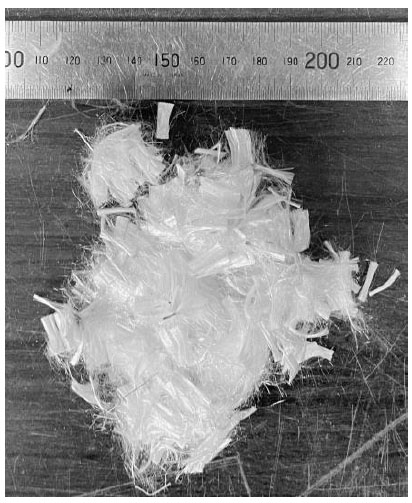
Image capture of Recron 3S polyester fiber utilized in the study.
| Type of Fiber | Density (g/cm3) | Diameter (μm) | Length (mm) | Tensile Strength (MPa) | Elastic Modulus (GPa) | Elongation (%) |
|---|---|---|---|---|---|---|
| Recron 3S polyester fiber | 1.36 | 30 | 12 | 460 | 5 | 20 |
2.2. Mix Proportion
This study used very fine sand with a size of less than 0.2 mm, Type II fly ash of Japanese Industrial Standard, and high early-strength Portland cement with a water-to-cement ratio of 56%. The fiber volume fraction was kept at 0%, 0.5%, 1%, and 2%, aiming for different composite performances. The details of the mix proportions followed in this study are presented in Table 2.
| Fiber Volume Fraction | W/C | FA/B | Unit Quantity (kg / m3) | |||||||
|---|---|---|---|---|---|---|---|---|---|---|
| Water | Cement | Fly Ash | Fiber | Sand | Super Plasticizer | Thickener | SR | |||
| 0% | 0.56 | 0.3 | 380 | 678 | 291 | 0 | 484 | 6 | 1.5 | 13.56 |
| 0.5% | 6.8 | |||||||||
| 1% | 13.6 | |||||||||
| 2% | 27.2 | |||||||||
2.3. Preparation of DFRCC and Casting of Specimens
A systematic mixing sequence was adopted to achieve the desired workability using a 60 L capacity vertical-axis pan-type mixer. Initially, cement, sand, and fly ash were dry-mixed for 1 min. The dosage of the superplasticizer was determined based on the total mixing water and was completely dissolved in the initial 95% of the mixing water before being added to the dry ingredients. The mixture was then mixed for 3 min to ensure uniform dispersion. Subsequently, the flowability of the mortar was evaluated using the J-funnel test. Based on the observed flow time, the remaining 5% of the mixing water, premixed with the thickener (viscosity-modifying agent), was added to adjust the workability, and the mixture was further mixed for 2 min. The flowability was then reassessed using the J-funnel test to confirm that the desired consistency had been achieved. Thereafter, Recron 3S polyester fibers were incorporated in two equal stages (50% of the total fiber content in each stage), with mixing carried out for 30 s after each addition to ensure uniform fiber distribution. Finally, the homogeneity of the mixture and the uniform dispersion of fibers were verified through visual inspection and manual assessment before casting. The results of the J-funnel test are given in Table 3.
| Fiber Volume Fraction (%) | 0% | 0.5% | 1% | 2% | |
|---|---|---|---|---|---|
| Fresh Mortar Temperature (°C) | 26.6°C | 26.4°C | 27.3°C | 28.1°C | |
| Thickener (g) | 45g | 45g | 45g | 45g | |
| Test results (s) | Without thickener | 19.37 | 22.25 | 20.31 | 22.00 |
| With thickener | 42.28 | 42.97 | 46.19 | 66.78 | |
Once the PES-DFRCC material is prepared, the workability is tested using a flow test. A standard flow cone, measuring 70 mm (top) to 100 mm (bottom) in diameter and 60 mm in height, is utilized for this purpose. The procedure involves packing the DFRCC material into the flow cone and lifting it vertically. The maximum diameter and the diameter perpendicular to it of the spread DFRCC are measured for each test. The average of these two diameters is then calculated. This process is repeated twice, and the average value from both attempts is taken as the final flow value. The test is conducted for all the fiber volume fractions, and the results are tabulated (see Table 4). Image capture of DFRCC mixes after the flow tests is presented in Fig. (2).
| Fiber Volume Fraction | 0% | 0.5% | 1% | 2% | |
|---|---|---|---|---|---|
| Attempt 1 | Maximum diameter (mm) | 338 | 260 | 175 | 104 |
| Right angle diameter (mm) | 321 | 246 | 152 | 103 | |
| Average diameter (mm) | 330 | 253 | 164 | 104 | |
| Attempt 2 | Maximum diameter (mm) | 368 | 269 | 174 | 111 |
| Right angle diameter (mm) | 346 | 245 | 169 | 107 | |
| Average diameter (mm) | 357 | 257 | 172 | 109 | |
| Flow value (mm) | 344 | 255 | 168 | 107 | |
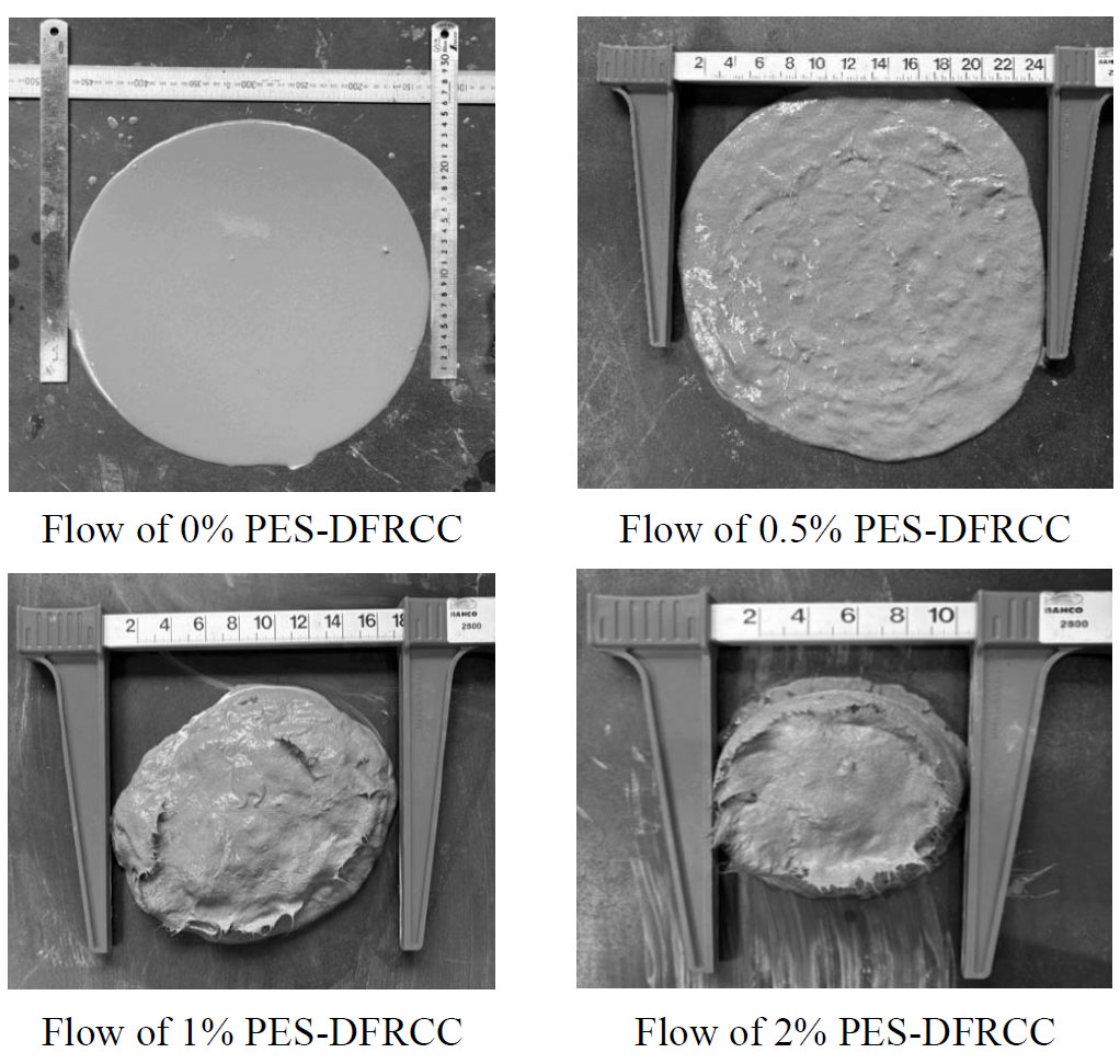
Images captured from flow tests of PES-DFRCC.
Fresh PES-DFRCC was then cast into the moulds in successive layers. Each layer was compacted using a tamping rod to ensure proper compaction and eliminate entrapped air, followed by surface finishing using a trowel to obtain a smooth and level surface. After demoulding, the cylindrical compression specimens were ground using a standard Japanese grinding machine to achieve plane and parallel loading surfaces prior to testing. Since high early-strength Portland cement was employed, the specimens achieved compressive strengths ranging from 44.1 MPa to 48.7 MPa within 9 days. Accordingly, all specimens were air-cured under laboratory conditions and tested at an age of 9 days.
2.4. Compression Test
Three cylindrical specimens, each with a diameter of 100 mm and a length of 200 mm, were cast for each fiber volume fraction to examine their compressive strength and elastic modulus. The specimens were identified using the PES-fiber volume fraction-specimen number format. After an adequate curing period, the cylindrical specimens were tested. The results from the compression tests for each specimen are presented in Table 5. The average compressive strength of PES-DFRCC varied from 44.1 MPa to 47.6 MPa. A representative compression specimen after testing is shown in Fig. (3).
| Specimen ID | Compressive Strength of each Specimen (MPa) | Average Compressive Strength (MPa) | Elastic Modulus of each Specimen (GPa) | Average Elastic Modulus (GPa) |
|---|---|---|---|---|
| PES–0%–C01 | 51.0 | 48.7 | 19.1 | 19.5 |
| PES–0%–C02 | 46.1 | 21.4 | ||
| PES–0%–C03 | 49.0 | 18.0 | ||
| PES–0.5%–C01 | 47.2 | 47.5 | 17.1 | 17.1 |
| PES–0.5%–C02 | 47.3 | 17.8 | ||
| PES–0.5%–C03 | 47.9 | 16.5 | ||
| PES–1%–C01 | 45.2 | 44.1 | 16.5 | 15.9 |
| PES–1%–C02 | 42.8 | 16.0 | ||
| PES–1%–C03 | 44.1 | 15.3 | ||
| PES–2%–C01 | 51.8 | 47.6 | 19.5 | 18.1 |
| PES–2%–C02 | 45.1 | 17.9 | ||
| PES–2%–C03 | 46.1 | 17.3 |
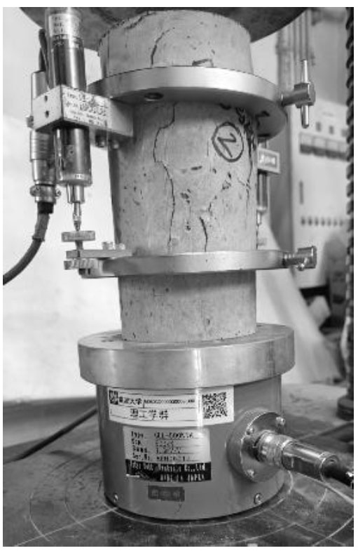
The specimens primarily exhibited longitudinal splitting cracks extending along the cylinder height, which are characteristic of compression-induced tensile splitting failure. Although multiple vertical cracks developed, the specimens remained largely intact without significant spalling or fragmentation. This behaviour is attributed to the crack-bridging action of the Recron 3S polyester fibers, which restricted crack widening and helped maintain the integrity of the composite after peak load. The elastic modulus of the compression specimens was evaluated from the stress–strain response obtained using LVDTs. The secant modulus was calculated as the slope of the line joining the origin and the point corresponding to one-third of the ultimate compressive strength for each specimen. The average elastic modulus for each mixture is reported in Table 5.
2.5. Four-Point Bending Test
A four-point bending test was conducted under ambient laboratory conditions at a temperature of 25 ± 2 °C on PES-DFRCC beam specimens to capture and examine the load-deflection and moment-curvature relationship. The dimensions of the beam specimens used in this study are 100 mm × 100 mm × 400 mm. Twenty beam specimens were cast and tested, using three fiber volume fractions: 0.5%, 1%, and 2%, along with a control group without fibers. The details of the beam specimens are given in Table 6. The bending test was conducted using a 500 kN universal testing machine, following the procedure outlined in the ISO 21914:2019 [25] standard. To measure axial deformations and deflection in the constant bending moment region, two π-type displacement transducers were placed on the specimen's front surface. In comparison, three linear variable displacement transducers (LVDTs) were positioned on the back surface, as illustrated in Fig. (4). The average curvature is calculated by determining the difference between the upper and lower strains based on the axial deformations.
| Specimen ID | Dimensions of Beam Specimens | Fiber Volume Fraction | Number of Specimens |
|---|---|---|---|
| PES–0%–B01 | 100 mm × 100 mm ×400 mm | 0% | 5 |
| PES–0%–B02 | |||
| PES–0%–B03 | |||
| PES–0%–B04 | |||
| PES–0%–B05 | |||
| PES–0.5%–B01 | 100 mm × 100 mm ×400 mm | 0.5% | |
| PES–0.5%–B02 | |||
| PES–0.5%–B03 | |||
| PES–0.5%–B04 | |||
| PES–0.5%–B05 | |||
| PES–1%–B01 | 100 mm × 100 mm ×400 mm | 1% | |
| PES–1%–B02 | |||
| PES–1%–B03 | |||
| PES–1%–B04 | |||
| PES–1%–B05 | |||
| PES–2%–B01 | 100 mm × 100 mm ×400 mm | 2% | |
| PES–2%–B02 |
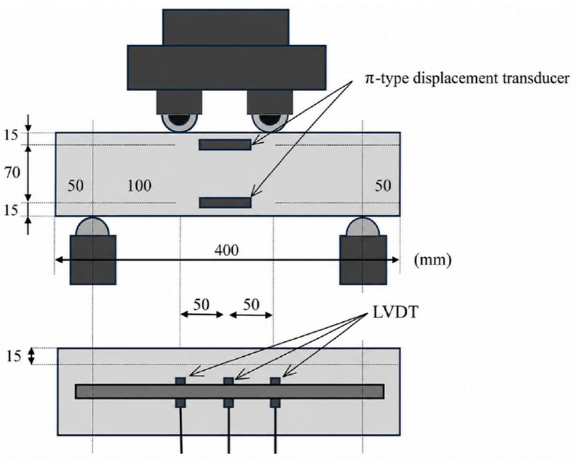
Setup of bending test.
3. RESULTS
3.1. Experimental Observation and Bending Performance of PES-DFRCC Beam Specimens
All control beam specimens (PES–0%–B01 to PES–0%–B05) exhibited a typical brittle response characterized by the formation of a single crack followed by sudden failure without any post-peak load-carrying capacity, achieving an average peak load of 6.6 kN. Incorporating 0.5% PES fibers transformed the response from brittle to deflection-hardening behaviour with multiple cracking, resulting in an average peak load of 10.8 kN. However, specimen PES–0.5%–B01 exhibited deflection-softening behaviour. Increasing the fiber volume fraction to 1% produced consistent multiple cracking and a deflection-hardening response in all specimens, with the average peak load increasing to 13.8 kN. Further increasing the fiber content to 2% maintained the multiple-cracking and deflection-hardening behaviour while achieving the highest average peak load of 23.4 kN. Although most beam specimens failed within the constant moment region, the final fracture occurred outside the loading region in specimens PES–0%–B02, PES–0%–B05, PES–0.5%–B01, PES–0.5%–B03, PES–2%–B03, and PES–2%–B05.
The beam specimens exhibited typical multiple-cracking behaviour as shown in Fig. (5). The failure of PES-DFRCC beam specimens is characterised by fiber slippage from the mortar in the main crack, ultimately resulting in pull-out failure, as shown in Fig. (6).
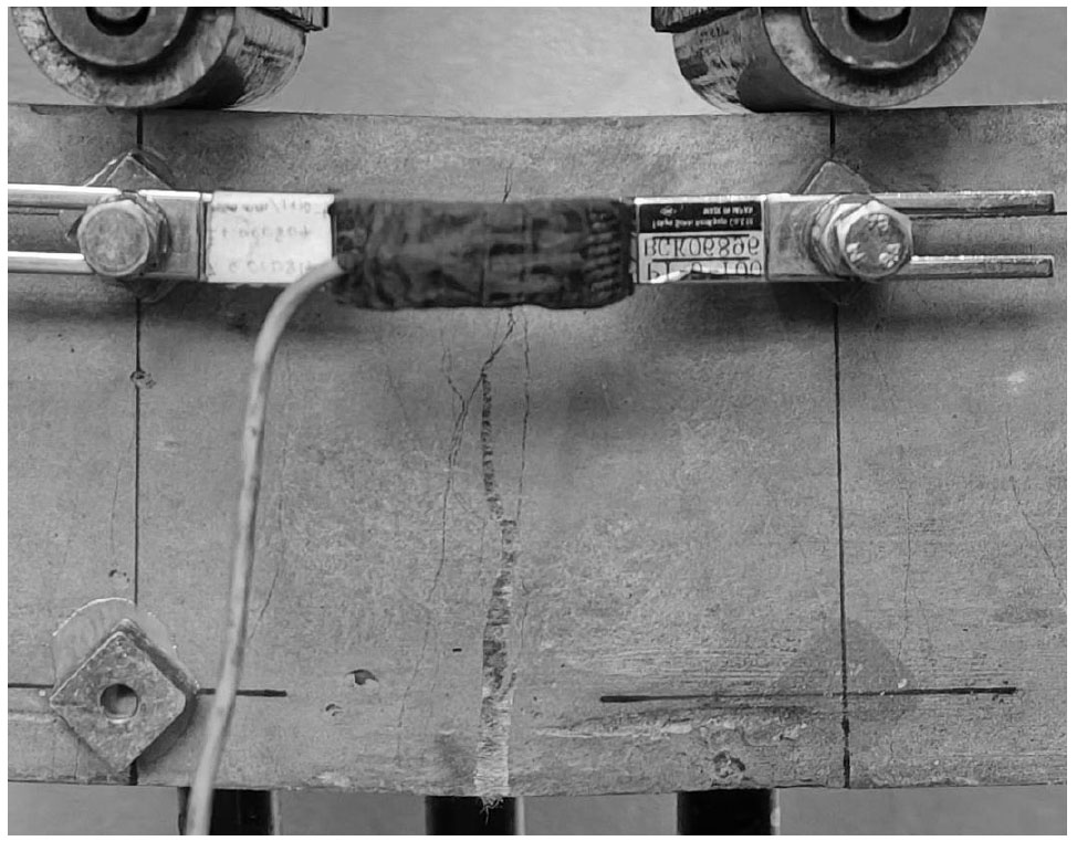
Typical multiple-cracking behaviour exhibited by PES-DFRCC beam specimens.
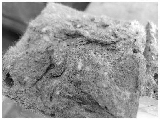
Pull-out failure of the PES-DFRCC beam specimen showing the exposed polyester fiber distribution on the fracture surface.
Figure 6 illustrates a representative fracture surface of the PES-DFRCC specimen after testing. Polyester fibers can be observed bridging the fractured matrix, demonstrating their crack-bridging capability. Although local variations in the number of exposed fibers are visible on the fracture surface, these are primarily attributed to the random orientation of the fibers and the crack propagation path through the specimen rather than non-uniform fiber dispersion. During specimen preparation, the fibers were incorporated in two equal stages after achieving the desired mortar workability and mixed thoroughly to ensure satisfactory dispersion throughout the cementitious matrix. No noticeable fiber balling or fiber agglomeration was observed during mixing or casting. The failure pattern of all tested beams is presented in Fig. (7).
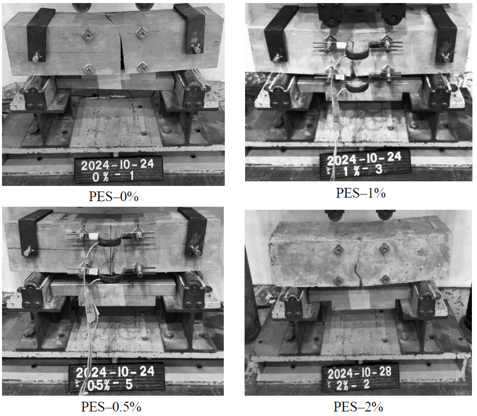
Failure pattern of beam specimens.
Figure 8a-d presents the measured load–deflection responses of all beam specimens, including those in which the final failure occurred outside the constant moment region. Most beam specimens exhibited a single peak load followed by a gradual post-peak softening response. However, distinct double-peak behaviour was observed in six specimens, namely PES-0.5%-B02, PES-0.5%-B03, PES-0.5%-B05, PES-1%-B02, PES-1%-B04 and PES-2%-B03. In these specimens, two distinct local maxima were observed during the pre-peak loading stage, with the second peak corresponding to the maximum (ultimate) load attained by the specimen. The occurrence of the first peak followed by a subsequent increase in load may be associated with progressive crack initiation and propagation, multiple-cracking development, and the progressive mobilization of fibre-bridging resistance. However, the precise mechanism governing the observed double-peak response cannot be conclusively established from the present experimental observations alone. The PES-0% specimens exhibited very limited deformation (Fig. 8a) of 0.02–0.04 mm, and the apparent non-zero load at zero deflection is attributed to an initial measurement/zero-reference offset. As its exact source could not be established retrospectively, this limitation should be considered when interpreting the initial response. The PES-1% specimens exhibited some variation in their load–deflection responses, which may be attributed to specimen-to-specimen differences in crack initiation and propagation, together with the random distribution and orientation of fibres and the resulting local fibre-bridging effects.
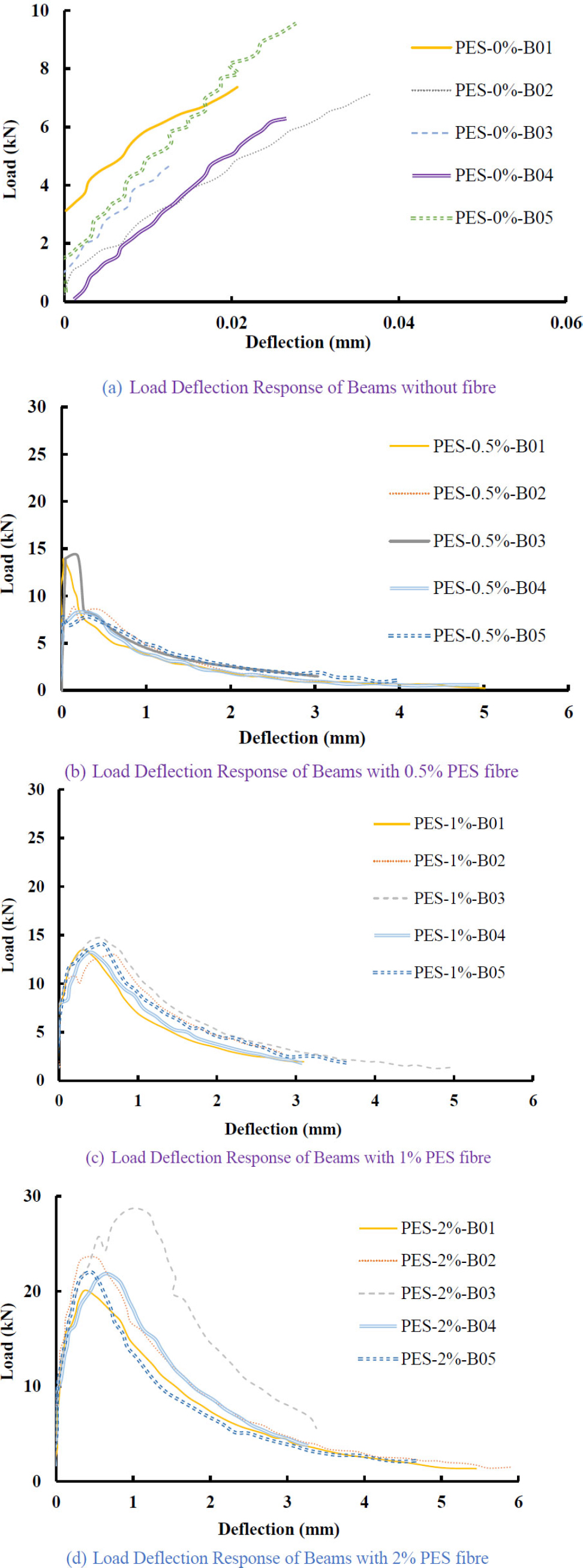
Load deflection response of all beam specimens.
3.2. Moment-curvature Relationship of PES-DFRCC Beam Specimens
For all beam specimens, axial deformations within the constant-moment (pure bending) region were measured on both the top and bottom surfaces using π-type displacement transducers, following the procedures specified in ISO 21914:2019 [25]. This standard applies to fibre-reinforced cementitious composites (FRCCs) that exhibit multiple separated cracks under pure bending before reaching the maximum load. Based on these measurements, the corresponding bending moment and curvature were calculated to establish the moment–curvature response.
As stated in the scope and illustrated in Fig. (1) of ISO 21914:2019 [25], the prescribed test method applies only to specimens in which the dominant crack and final failure occur within the constant-moment region. Specimens exhibiting dominant cracking outside the constant-moment region are explicitly classified as not applicable under the standard because their response is influenced by stress states other than pure bending.
Accordingly, the moment–curvature analysis presented in this study was performed only on beam specimens satisfying the applicability requirements of ISO 21914:2019 [25], namely those exhibiting final failure within the constant-moment region. Although five beam specimens were tested for each mixture, the specimens exhibiting dominant cracking and final failure outside the constant-moment region were classified as not applicable according to ISO 21914:2019 [25] and were therefore not considered for the moment–curvature comparison or the subsequent inverse analysis used to determine the tensile characteristics of PES-DFRCC. Consequently, the number of moment–curvature curves presented in Fig. (9a-d) varies from three to five, depending on the number of specimens satisfying the applicability requirements of the standard.
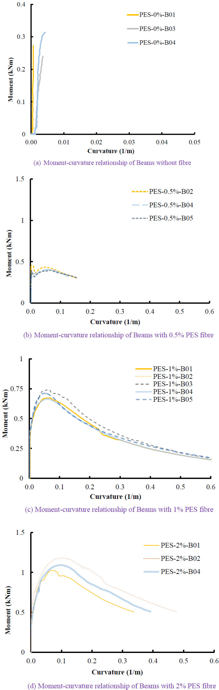
Moment–curvature responses of beam specimens exhibiting final failure within the constant-moment region.
3.3. Evaluation of Tensile Properties of PES-DFRCC
The key characteristic of DFRCC is its ability to harden under deflection after the first crack occurs. This remarkable property should be utilised in the design of structural members. Therefore, evaluating the tensile properties of DFRCC is essential. Unlike ECC, which demonstrates tensile strain hardening through uniaxial tension tests on coupon specimens, DFRCC does not always exhibit strain hardening behaviour in tension, making uniaxial tension tests unsuitable for assessing its tensile properties. To effectively evaluate the tensile properties of DFRCC, Kanakubo [8] introduced an inverse method involving sectional analysis based on beam theory.
The present study utilises the same evaluation method as previous research. The following assumptions are made for the inverse analysis: 1. During bending, the stress distribution of DFRCC on the tension side is assumed to be bilinear, characterised by four unknown parameters: first crack strength, first crack strain, ultimate strength, and ultimate strain. 2. The stress distribution of DFRCC on the compression side is considered linear elastic up to failure since the compressive strength is significantly higher than the tensile strength. 3. Plane sections are assumed to remain plane before and after bending, ensuring compatibility of strains. 4. The equilibrium of forces is maintained at both the first crack and ultimate failure. 5. At the ultimate level, since the ultimate strain is several tens of times greater than the crack strain, the elastic region is neglected, and a simplified equilibrium equation is derived by assuming a linear stress distribution. Figure 10 illustrates the strain and stress distribution across the beam cross-section.
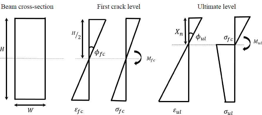
Strain and stress distribution of the beam section.
By designating the height and width of the beam as H and W, the young’s modulus, tensile strain, and tensile stress at the first crack are calculated as per Eqs. (1, 2 and 3).
At the first crack,

The tensile strain of DFRCC at the first crack,

The tensile stress of DFRCC at the first crack,

here E is the elastic modulus, Mfc is the moment at the first crack, φfc is the curvature at the first crack. At the ultimate level, ultimate tensile strain (εul) and ultimate tensile stress (σul) of the PES-DFRCC is calculated following strain compatibility and force equilibrium conditions, by solving Eqs. (4 and 5).


here φul is the curvature at ultimate, Xn is the depth of the neutral axis, Mul is the moment capacity of the beam at ultimate. Table 7 presents the calculated stress and strain of all PES-DFRCC mix proportions at first crack and ultimate conditions. Figure 11a-c gives all specimens' equivalent tensile stress-strain curves for PES-DFRCC, including an average curve. These curves are generated using the evaluated tensile stress and tensile strain values. The equivalent average stress–strain response for each PES-DFRCC mixture shown in Fig. (12) was obtained by averaging the equivalent tensile stress and the corresponding strain values of the valid beam specimens.
| DFRCC | First Crack Strength | First Crack Strength /Strain | Tensile Strength | Ultimate Strain | ||||||||
|---|---|---|---|---|---|---|---|---|---|---|---|---|
| Avg. (MPa) | SD (MPa) | COV (%) | Avg. (GPa) | SD (GPa) | COV (%) | Avg. (MPa) | SD (MPa) | COV (%) | Avg. (%) | SD (%) | COV (%) | |
| PES–0.5%-B | 1.97 | 0.15 | 7.4 | 23.8 | 11.2 | 47.2 | 0.34 | 0.04 | 12.5 | 0.276 | 0.059 | 21.4 |
| PES–1%-B | 2.16 | 0.25 | 11.3 | 43.9 | 18.5 | 42.0 | 1.16 | 0.17 | 14.8 | 0.318 | 0.033 | 10.4 |
| PES–2%-B | 2.53 | 0.33 | 12.9 | 23.9 | 8.2 | 34.0 | 2.41 | 0.05 | 2.2 | 0.450 | 0.097 | 21.8 |
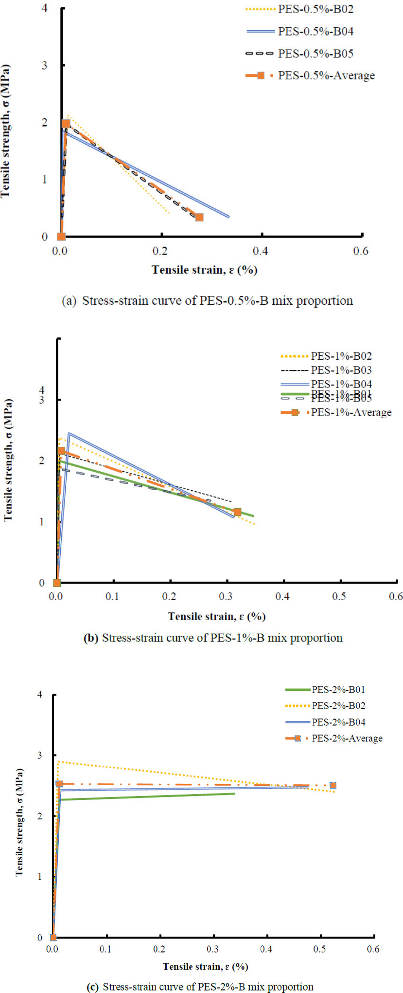
Equivalent stress-strain response of PES-DFRCC mix proportions.
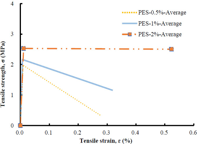
Equivalent average stress-strain response of PES-DFRCC mix proportions.
4. DISCUSSIONS
4.1. Tensile Stress – Strain Response of DFRCC
The beam specimens without polyester fibers exhibited sudden brittle failure immediately after first cracking and showed virtually no post-peak load-carrying capacity, as expected. In contrast, the PES-DFRCC beam specimens exhibited a pronounced deflection-hardening response, which became progressively more evident with increasing fiber volume fraction. The specimens containing 2% polyester fibers achieved the highest load (moment) capacity and the greatest post-cracking deformation capacity. This improvement is attributed to the crack-bridging action of the polyester fibers, which enabled continued load transfer across cracks and promoted the formation of multiple microcracks (Fig. 7).
Although flexural cracks developed in all fiber-reinforced specimens, the extent of multiple microcracking varied among specimens with the same fiber content because of the inherent variability associated with crack initiation and propagation in cementitious composites. Nevertheless, specimens exhibiting greater deflection-hardening behaviour generally developed a larger number of fine cracks, particularly at higher fiber volume fractions. It should be noted that deflection hardening does not necessarily imply strain hardening, since deflection hardening represents the structural response of the beam, whereas strain hardening describes the constitutive tensile response of the material.
The equivalent tensile stress–strain curves obtained through inverse analysis indicated that all PES-DFRCC mixtures exhibited tensile strain-softening behaviour after first cracking. However, the degree of strain softening progressively decreased with increasing fiber volume fraction. In particular, the mixture containing 2% polyester fibers exhibited an almost flat post-cracking tensile response, indicating a substantial reduction in strain softening compared with the lower fiber volume fractions (Fig. 12). This trend is generally consistent with the uniaxial tensile test results reported by Kumar and Rai [24], who used the same polyester fibers with a different matrix composition and observed moderate tensile strain-hardening behaviour.
Compared with the PVA-DFRCC reported by Kanakubo [8], which exhibited clear tensile strain-hardening behaviour, the PES-DFRCC investigated in the present study demonstrated tensile strain softening. This difference may be attributed to the combined influence of the comparatively lower tensile strength and elastic modulus of the polyester fibers, together with their fiber–matrix interaction characteristics. These factors are likely to promote progressive fiber pull-out during crack propagation, thereby limiting stress transfer across cracks and resulting in tensile strain-softening behaviour. Nevertheless, the observed reduction in strain softening with increasing polyester fiber content demonstrates that enhancing the crack-bridging capacity of the fibers can significantly improve the post-cracking tensile response of PES-DFRCC.
4.2. Future Research Perspective
Although the polyester fibers used in the present study significantly improved the flexural performance of PES-DFRCC, the inverse analysis indicated that all mixtures exhibited tensile strain-softening behaviour after first cracking. Based on the experimental observations, this behaviour may be associated with the combined influence of the comparatively lower tensile strength, lower elastic modulus, and fiber–matrix interaction characteristics of the polyester fibers, which may promote fiber pull-out during crack propagation. Future research should therefore focus on optimizing the fiber–matrix interface through approaches such as reducing the fiber diameter, applying suitable surface modifications (e.g., hydrophilic coatings), investigating hybrid or alternative fiber configurations, and evaluating their influence on crack-bridging behaviour. However, any enhancement in interfacial bond strength should be carefully balanced against the relatively low tensile strength of the polyester fibers, since an excessively strong bond may promote premature fiber rupture rather than controlled fiber pull-out. In addition, systematic investigations on the effects of fiber diameter, surface modification, and hybridization on fresh-state workability, fiber dispersion, crack development, and the resulting tensile and flexural performance are required to optimize the overall behaviour of PES-DFRCC. Future studies should also include microscopic characterization of the fiber–matrix interface, such as scanning electron microscopy (SEM) and single-fiber pull-out tests, to better understand the governing failure mechanisms and validate the proposed explanations for the observed tensile response. Furthermore, the equivalent tensile properties obtained through four-point bending inverse analysis should be validated against direct uniaxial tensile test results for the same PES-DFRCC mixtures, thereby establishing the reliability of the proposed methodology as a practical and economical alternative for tensile characterization. Finally, comprehensive techno-economic and environmental assessments, including material cost analysis and life-cycle assessment, should be undertaken to quantify the economic viability and sustainability benefits of PES-DFRCC in comparison with conventional PVA- and PE-based DFRCC systems for practical infrastructure applications.
4.3. Limitations of the Study
The present study is limited to one cementitious matrix and one polyester fibre type. Four fibre volume fractions, including the control mixture, were investigated with five beam specimens per mixture. The tensile properties were evaluated using inverse section analysis and are therefore dependent on the adopted analytical assumptions. Specimens exhibiting failure outside the constant-moment region were classified as not applicable according to ISO 21914:2019 and excluded from the moment–curvature and inverse analyses. The occurrence of such failures may also be influenced by the testing machine and experimental configuration. Direct uniaxial tensile testing was not performed for the same PES-DFRCC mixtures, and independent validation of the evaluated tensile properties is therefore required. Further studies involving different matrices, fibre characteristics, and independent tensile testing are needed to validate and generalize the present findings.
CONCLUSION
This study evaluated the bending performance of polyester fiber-reinforced ductile fiber-reinforced cementitious composite (PES-DFRCC) and, for the first time, reported its equivalent tensile properties through a simple inverse analysis based on beam theory. The results demonstrate that Indian-manufactured polyester fibers are suitable for producing PES-DFRCC with satisfactory workability. Among the mixtures investigated, a fiber volume fraction of 2% resulted in the lowest workability while still maintaining acceptable fresh properties, whereas higher fiber contents may adversely affect workability for moderate-strength (45–50 MPa) DFRCC.
Under four-point bending, the PES-DFRCC beam specimens generally exhibited deflection-hardening behaviour, except for PES–0.5%–B01, which showed deflection-softening. Increasing the polyester fiber content generally enhanced the deflection-hardening response, resulting in higher moment capacity and greater post-cracking deformation capacity.
The inverse analysis further indicated that all mixtures exhibited tensile strain-softening behaviour after first cracking; however, the degree of strain softening progressively decreased with increasing fiber content, with the 2% fiber mixture exhibiting an almost flat post-cracking tensile response. These findings are consistent with previously reported uniaxial tensile test results for the same polyester fiber, despite differences in mix proportions, demonstrating that the proposed inverse analysis provides a practical approach for evaluating the tensile behaviour of PES-DFRCC from flexural test data.
AUTHORS’ CONTRIBUTIONS
The authors confirm their contribution to the paper as follows: T.K.: Study conception and design; S.F. and H.N.S.: Acquisition of data; H.K., M.VR.S. and T.K.: Analysis and interpretation of data; M.VR.S, T.K. and S.B.S.: Drafting of manuscript. All authors reviewed the results and approved the final version of the manuscript.
LIST OF ABBREVIATIONS
| DFRCC | = Ductile Fiber Reinforced Cementitious Composite |
| ECC | = Engineered Cementitious Composite |
| FRCC | = Fiber Reinforced Cementitious Composite |
| HPFRC | = High-Performance Fiber-Reinforced Cementitious Composite |
| MPC | = Magnesium Phosphate Cement |
| PE | = Polyethylene |
| PET | = Polyethylene Terephthalate |
| PES | = Polyester Fiber |
| PVA | = Polyvinyl Alcohol |
| SHCC | = Strain-Hardening Cementitious Composite |
AVAILABILITY OF DATA AND MATERIALS
The data supporting the findings of this study are available from the corresponding author, Dr. Madappa V. R. Sivasubramanian, upon reasonable request. The data have not been deposited in a public repository; therefore, no public dataset link is available.
FUNDING
This research study is mainly supported by the India-Japan collaborative science program (2024-2026), funded by DST India and JSPS Japan, for BITS-Pilani, India, and the University of Tsukuba, Japan. It also receives partial funding from the National Technical Textiles Mission (NTTM), Ministry of Textiles, Government of India, through a major research project at NIT Puducherry.
ACKNOWLEDGEMENTS
The laboratory experiments for this research were conducted at the RC Laboratory at the University of Tsukuba, Japan.